MICrODEC
Modularizing
The MICrODEC is a very flexible sound modulating platform. It can act as a VCO, VCA, VCF, or any sort of strange contraption you can think of. This makes it particularly handy for modular synthesizers, with the added benefit that it won't drift with temperature! Below are some modifications that can be made to the MICrODEC to incorporate it into a modular platform.
Power
Modular synths generally run a positive voltage rail of either 12V or 15V. A common 7809 voltage regulator can be used to step this down to the ~9V the MICrODEC was designed for. The MICrODEC draws roughly 75mA between its 5V and 3.3V rails. This means it will dissipate around 750mW with a 15V input. That gets the MICrODEC's regulators pretty hot to the touch, but not enough to necessitate a heat sink unless you so desire. Here's a simple way to step the voltage down to a safer level.

Input Attenuation
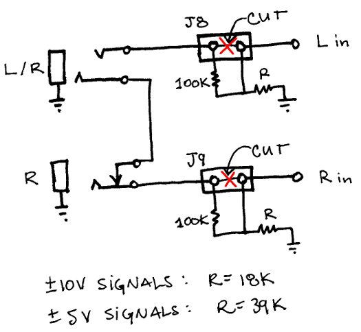
This will allow the MICrODEC to accept the higher voltages common with modular synthesizers. The schematic also shows how to split the single stereo jack into 2 jacks, one for left and right, so seperate signals can be processed. NOTE: some of the stock functions do not use the right channel.
Output Amplification
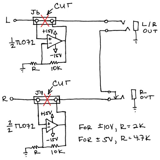
This will boost the MICrODEC signals to +/-10V or +/-5V, depending upon what your system requires. The schematic also shows how to split the single stereo jack into 2 jacks, one for left and right, so seperate signals can be processed.
CV input to MOD1
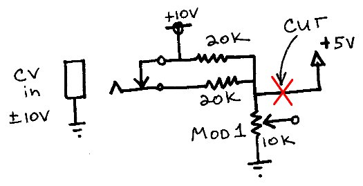
This is a quick hack to allow the MOD1 knob to be controlled by an external CV. It has the benefit of still using the MOD1 knob to control the gain of the signal you are inserting. The only drawback is that the DC level is also reduced as you turn down the gain. An op-amp circuit would be required to decouple gain and offset. The schematic is for +/-10V signals. Different resistor values would be required for different signal levels.
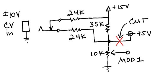
5U format modulars (MOTM, Synthesizers.com, Modcan, etc.) can fit the board comfortably and the modifications are quite straightforward --- 2 resistors and an input jack. The MICrODEC PCB is taller than the 3U (5.25") height of Eurorack and Frac Modular formats. With the exception of Moog, all 5U formats use +/- 5V signals (10VPP) for both audio and CV, and run +/-15V power rails. For +/-5V signals (10VPP), 2 resistors, 6.8K and 20K, can be soldered between the input jack, 15V, and Mod1 pot as pictured. A Switchcraft 112A is a good choice of jack if you're patching with 1/4" cables.
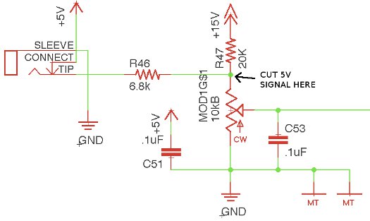
If the Mod1 pot is mounted off board, no traces need to be cut and adding external CV control to Mod1 is surprisingly simple. The 5V lead from the PCB to the pot can be instead routed to the switch lug of the CV input jack. As such, nothing needs to be soldered to the PCB and the Mod1 pot acts as an attenuator for external CV signals up to +/-5V. However, please take care not to exceed this voltage range. Also, there's two things to keep in mind with this mod. C53 is still acting as a 6dB/octave lowpass filter on the CV input. When the mod pot is fully open to the incoming signal, the -3dB point is at 62 Hz. If your bothered by some modulation at audio rates is getting bypassed, replace C53 with a smaller value. Second, the CV input impedance is lower than most other modular inputs, so your signal needs enough juice to drive it. For 1Kohm sources, the DC loss due to loading is 0.5dB, less if you up the value of the Mod1 pot. In practice, it's probably best to try this mod with just adding the two resistors and input jack, then worry about these details if they worry you.
