x0x-heart pacemaker (Eurorack adapter board)
About the pacemaker
The pacemaker is the shortest path to getting your x0x-heart beating in your modular setup. It pins out all of the knobs, and allows for CV control of frequency, gate, accent, slide, env-mod, decay, and cut-off. There are also switches for waveform select, external oscillators, and both the VCA and VCF outputs are available. The front panel was designed by Grayscale.
Design notes / mods
A few tradeoffs were made in the design of the pacemaker. Most of these were done in hopes of making it easy and inexpensive to build, at the cost of some component fiddling. So, as you build, you can modify your pacemaker to suit your needs.
- CV to PWM converter - This is probably the most finicky part of the circuit. A microcontroller would have been a better solution, except that would have required things that most people do not have on hand. So, instead it is based on a 555 timer. But, it is being run at a frequency in its upper limits, so it does not behave the same across all 555 timers. If you are picking up some new 555's, be sure to get an LM555 from Fairchild, as these are what the pacemaker was designed around. But don't worry if you don't have that exact part, it will still work. Just be sure to follow the test procedure in the Assembly tips below.
- VCA gain - The output of the x0x-heart varies greatly depending upon how it is being run. If the resonance is down, or accents are triggered, the output can be 10x that of other conditions. To accomodate for this a large gain was put on the VCA output stage, with the volume knob attenuating the signal before the gain stage. The gain is set by R29, for which the default (2.2k) ensures that even the smallest signal can be boosted to +/-5V. But, this means that the noise floor is also boosted, so for high level signals, where the volume pot will need to be turned down, there will be more noise than otherwise. So, if you want to increase the SNR at the expense of not getting full volume for 100% of the case, you can increase R29. A value of 10k would probably be fine 90% of the time.
- VCF gain - Since the VCF does not have a volume control, and the output also varies depending upon cutoff frequency and resonance, its gain was set so that its loudest signal would not clip. This means that average signals will be lower (usually half the amplitude). The gain of the VCF amplifier is set by R26 with a default of 12k. You can drop this value to 10k (and increase the gain) without much worry of distortion.
- VCF mix - Another possible solution to the VCF amplitude problem is to adjust the VCF input mix. As the resonance is turned up, the amplitude of the VCF output drops. By mixing some of the signal from the resonance pot wiper, you can get an increase in signal as the resonance is turned up. A mix of 2:1 is used on the VCF output (same as is used internally in the 303 to feed the VCA). These are set with R30 and R34. Dropping R30 to 100k gives a more consistent amplitude over the resonance range.
Assembly tips
You may want to build your pacemaker in the following order, to make it easier to solder.
- Solder female 0.1" SIP headers on the x0x-heart (All pot headers, J2, J7, J8). Be sure to keep them well aligned and vertical.
- Place male 0.1" SIP headers into the female headers (same as above), and then place the pacemaker onto the other side of the male headers. Now solder them in place. This will ensure accurate alignment between the boards.
- Solder remaining components to the bottom of the pacemaker (U6, C10, C11, J0).
- Solder in the CV to PWM components (U3, U2, C1, C2, C4, C8, C13 (C13 might need to be laid flat), R1 - R10.). If you have the option, use an LM555 from Fairchild, as the circuit was designed around this. If you do not have one handy, don't worry, any imperfections can be accounted for in the next step.
- Solder in the ENVMOD channel of input components (D1, R11, R12, R35, R39).
- Check that the ENVMOD PWM works adequately. Apply power at J0, and check U6 with a multimeter: 1 pin should be 12V, the middle pin 0V, and the other pin 5V. Next, apply a CV to the ENVMOD input (you can solder on the 1/8" jack if it makes it easier). Monitor the voltage output of J3-pin6 (labeled pin3 on the schematic / pin6 on the silkscreen) as you sweep the CV in from 0V to 5V. The PWM out should go from 0% to 100% (the actual design is 0.5V to 4.5V, so anything around there is fine). If you do not have an oscilloscope to watch the PWM waveform, you can put your multimeter on the output, and see when it starts changing. it will be around 0.2V at the beginning, and this will start increasing when the PWM goes above 0%. it will then top out at 4.9V when it hits 100%.
- If your PWM doesn't match this, the R35/R39 pair will need a bit of tweaking. If the PWM comes on too early, then it needs to be shifted down by reducing R35. If it comes on too late, then it needs to be shifted up by reducing R39. If any adjustment is needed, it will be small (for example, adjusting R39 from 51k to 47k).
- Solder in the remaining channels once you have verified that the values you have chosen work well. In most cases the default values will be just fine.
- Solder in the remaining ICs and passive components.
- Place the jacks, switches and pots, and attach the faceplate. Then solder the jacks and such in. This will ensure that they are perfectly aligned.
- Run jumper wires for the remaining headers which do not directly mate to the x0x-heart. The header pins are labelled with J(N), and match the x0x-heart board. The pin numbers on the pacemaker match the pins they go to on the x0x-heart. Be very careful with J1, as the pin assignments go from left to right, and then top to bottom, and NOT counter-clockwise as a typical DIP component would. See the images below if you are not sure.
- Test to see if everything works. Rinse and repeat.
- Wash the flux off the board.
Tuning the x0x-heart after installation
The manual lists the tuning procedure for standalone operation. Unfortunately, when the x0x-heart was originally designed, there was no intent to make a kit out of it, so the when the Pacemaker finally came around, there were some really awkward design constraints. As a result, all the tuning pots are nearly impossible to access while the unit is assembled. The easiest way around this, is to disconnect the Pacemaker, but leave the jumpers in place. Next, run jumpers for J8, RES1 (set to mid), TUNE (set to mid), and CUTOFF (set to full up), and measure the frequency at the VCF output. its safer to do it this way as well, as its less likely that something will short.
Assembly images (hopefully better ones coming soon)
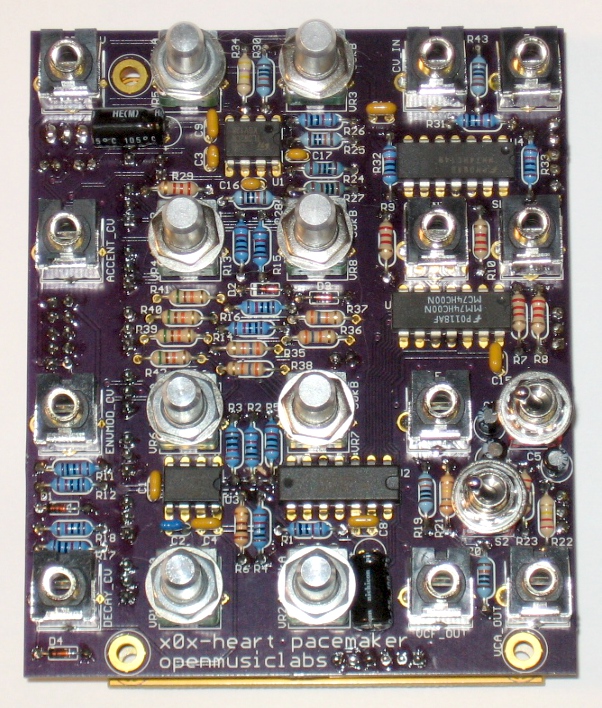
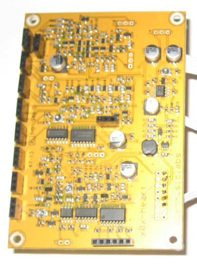
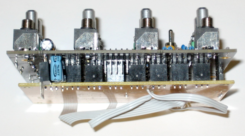
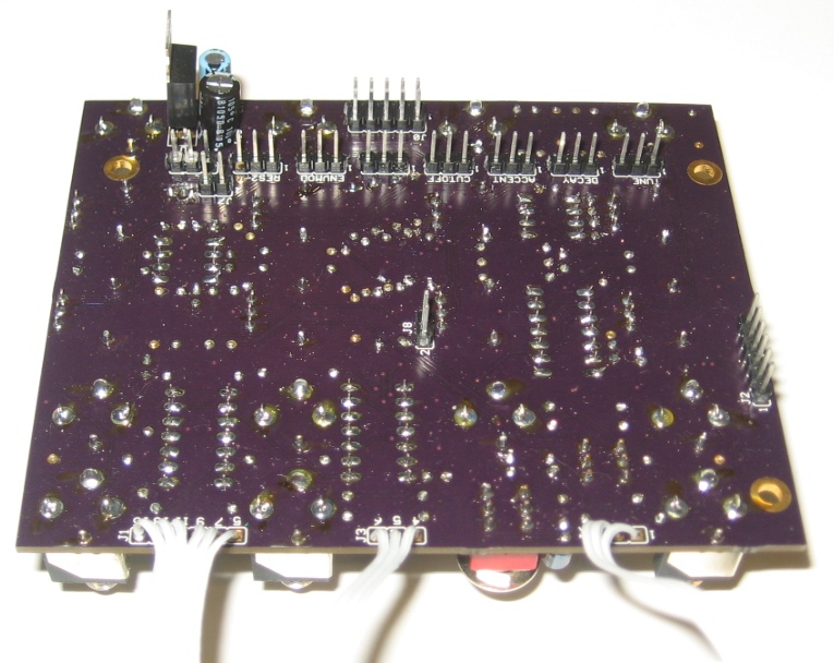
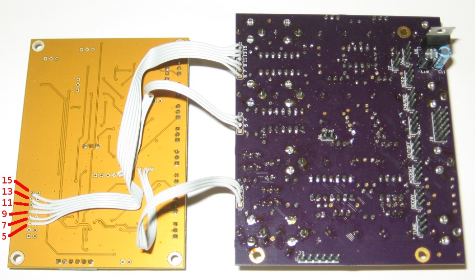
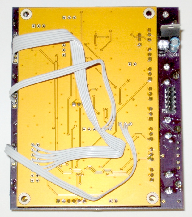
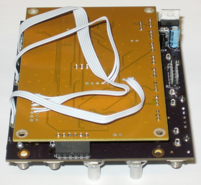
Design files
Through Hole board
The Mouser cart has the minimum quantites to do a single build (minus the pots/jacks/switches). It does NOT include IC sockets, so be sure to pick these up if you need them. The price break on the resistors is at 200, if you want to pick up a whole bag. And i would reccomend getting at least 2 of the 0.1" male SIP header, as it often breaks at the wrong point, giving a useless length.
