|
Size: 3494
Comment:
|
Size: 4459
Comment:
|
| Deletions are marked like this. | Additions are marked like this. |
| Line 7: | Line 7: |
| ==== How to Use the SineCore Modulator ==== |
==== How to use the SineCore Modulator ==== ===== Pinout ===== |
| Line 9: | Line 10: |
| The module comes in a 14P Wide-DIP format. The pins are labeled 1 to 7 from top to bottom on 2 headers, J1 and J2. Don't ask me why its that way as compared to the conventional labeling of 1 to 14, as there is no good reason. The pins are as follows: | The module comes in a 14P Wide-DIP (0.7" spacing) format. The pins are labeled 1 to 7 from top to bottom on 2 headers, J1 and J2. Don't ask me why its that way as compared to the conventional labeling of 1 to 14, as there is no good reason. The pins are as follows: |
| Line 11: | Line 12: |
| {{}} | {{attachment:sinecore_part_sm.png}} |
| Line 29: | Line 30: |
|
===== Bias current control ===== The bias current controls the amplitude of the output signal. This can either be fixed or varied. It's good to keep the bias current between 100uA to 200uA for optimal distortion performance, but it can be as high as 1mA without too much degredation. The bias current can either be set with the onboard reference and output transistor, or with an external source tied to J1-pin4. The bias and output transistor can be used as a simple current mirror for linear control, or set up as an exponential pair for exponential control. The output transistor can also be driven directly with an opamp for linear control. ===== Width current control ===== The SineCore Modulator implements the function V,,out,, = sin(A*V,,in,,). The width current sets the gain factor 'A' in this equation, which is effectively the number of folds per volt of input signal. |
SineCore Modulator
About the SineCore Modulator
The SineCore Modulator is based on a design by Barrie Gilbert from 1977. It uses a series of cascaded differential amplifiers to smoothly change the polarity of the output signal as the input voltage is increased. This became the basis for the AD639 "Universal Trigonemtric Function Converter" IC from Analog Devices, Inc. The SineCore Modulator can produce +/-720 degrees of a relatively low distortion sinewave. Over the first +/-90 degrees, the THD is around -80dB, making it very useful for triangle or sawtooth to sinewave conversion. If the amplitude of the input signal is modulated, the number of reversals increases, essentially acting as a quadruple wavefolder. When a sawtooth wave is applied, it can be summed with a DC offset to produce sinewave Phase Modulation (PM) with through-zero capability.
How to use the SineCore Modulator
Pinout
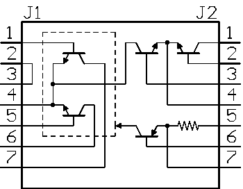
The module comes in a 14P Wide-DIP (0.7" spacing) format. The pins are labeled 1 to 7 from top to bottom on 2 headers, J1 and J2. Don't ask me why its that way as compared to the conventional labeling of 1 to 14, as there is no good reason. The pins are as follows:

Pin |
Function |
|
J1 |
1 |
Positive input - base of modulator transistor |
2 |
Shield - connect to ground if used |
|
3 |
Shield - connect to ground if used |
|
4 |
Alternate bias current control - emitters of modulator transistors |
|
5 |
Negative input - base of modulator transistor |
|
6 |
Negative outout - collectors of modulator transistors |
|
7 |
Positive output - collectors of modulator transistors |
|
J2 |
1 |
Bias current control - collector of reference transistor |
2 |
Bias current control - base of reference transistor |
|
3 |
Bias current control - base of output transistor |
|
4 |
Bias current control - emitters of reference and output transistors |
|
5 |
Width current control - supply voltage input |
|
6 |
Width current control - base of output transistors |
|
7 |
width current control - emitter of reference transistor |
|
Bias current control
The bias current controls the amplitude of the output signal. This can either be fixed or varied. It's good to keep the bias current between 100uA to 200uA for optimal distortion performance, but it can be as high as 1mA without too much degredation. The bias current can either be set with the onboard reference and output transistor, or with an external source tied to J1-pin4. The bias and output transistor can be used as a simple current mirror for linear control, or set up as an exponential pair for exponential control. The output transistor can also be driven directly with an opamp for linear control.
Width current control
The SineCore Modulator implements the function Vout = sin(A*Vin). The width current sets the gain factor 'A' in this equation, which is effectively the number of folds per volt of input signal.
Over-voltage Protection
There is the risk of damage to the module if the Vbe of the modulator transistors are reverse biased more than 6V. I have routinely driven them well past this without damage (up to 20V), but if you want to be safe, the positive and negative inputs (J1 pins1,5) should never differ by more than 6.6V. There are tradeoffs between various protection schemes between current consumption during the over-voltage period, steepness of the transition region, and the bandwidth of the circuit. For this application, speed is necessary as the sharpness of the triangle or saw wave determine its accuracy. Any rounding off of the peaks will cause distortion. For this reason, i would reccomend series connected, 5.6V zener diodes between the 2 inputs pins (maybe, need to check this).
