Analysis of Diodes for Voltage Clamping
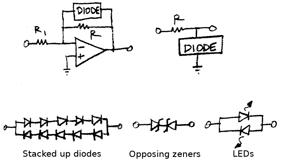
There are a number of different ways to limit the voltage at a particular point in a circuit. Two common ones are shown below. These use the turn-on voltage of a diode to limit current flow below a certain threshold, and to clamp the voltage above that threshold. The first circuits shows the diodes in the feedback loop of an opamp, and the second just uses a resistor (R) to limit the current when the diodes turn on. Three different diode clamps are shown directly below this, with the first being a stack of normal diodes, the second being back to back zeners, and the third using LEDs.

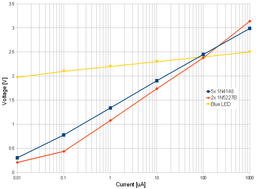
It is often desirable to have a hard cut-off in the clamping circuit. In this case, the diodes do not effect the circut at all below the clamp voltage (they draw no current and create no distortion), and above the clamp voltage they act as a short, holding the output fixed regardless of the input. The three different diode configurations shown above were tested for their voltage-current relationships, to see how well they would perform in voltage clamping applications. A graph of their performance is shown below:

