|
← Revision 5 as of 2017-03-28 23:02:39
Size: 1241
Comment:
|
← Revision 6 as of 2017-03-28 23:27:33 →
Size: 2910
Comment:
|
| Deletions are marked like this. | Additions are marked like this. |
| Line 2: | Line 2: |
| ==== Overview ==== | |
| Line 10: | Line 10: |
|
==== Diode Capacitance ==== Although the 1N4148 diodes faired poorly in comparison to the blue LEDs in terms of forward current, they have one very large advantage over the zener diodes or LEDs: low capacitance. The capacitance of the clamping circuit works in parallel with the resistor (R) to low-pass filter the signal. This filter may be an issue, depending upon the bandwidth required by the circuit. For accurately passing sawtooth or square waves, banwidth into the MHz range is required. To limit this effect, either R or C needs to be reduced. There are limitations on how small R can become due to output current of the opamp and the gain required by the circuit. So, if C needs to be as small as possible, the 1-3pF capacitance of the 1N4148 diode might be required. This capacitance is even further reduced by the fact that the diodes are in series, so the capacitance adds in parallel. In the example above, if each diode was 3pF, the total capacitance of a single string would be 3/5pF, and both strings in parallel would give 6/5pF. On the other hand, both the zener diodes and LEDs have capacitance in the 100-200pF range. The zener is better choice here, as its capacitance is halved, as there are two in series, whereas the LED capacitance is doubled, as the two are in parallel. ==== Leakage Current ==== Besides for conducting current when there is a small forward voltage across them, diodes also leak a bit of current when they are reverse biased. This leakage current is not a problem for the zener configuration, as the diodes are in series, so there is no leakage path. For the LED and 1N4148 setups, |
Analysis of Diodes for Voltage Clamping
Overview
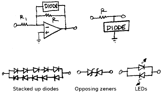
There are a number of different ways to limit the voltage at a particular point in a circuit. Two common ones are shown below. These use the turn-on voltage of a diode to limit current flow below a certain threshold, and to clamp the voltage above that threshold. The first circuits shows the diodes in the feedback loop of an opamp, and the second just uses a resistor (R) to limit the current when the diodes turn on. Three different diode clamps are shown directly below this, with the first being a stack of normal diodes, the second being back to back zeners, and the third using LEDs.

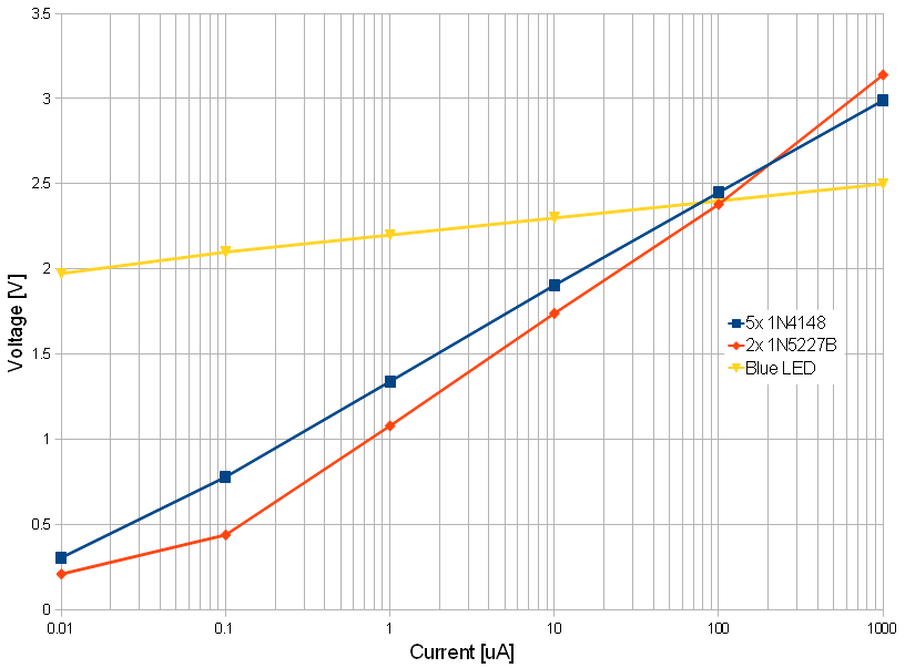
It is often desirable to have a hard cut-off in the clamping circuit. In this case, the diodes do not effect the circut at all below the clamp voltage (they draw no current and create no distortion), and above the clamp voltage they act as a short, holding the output fixed regardless of the input. The three different diode configurations shown above were tested for their voltage-current relationships, to see how well they would perform in voltage clamping applications. A graph of their performance is shown below:

Diode Capacitance
Although the 1N4148 diodes faired poorly in comparison to the blue LEDs in terms of forward current, they have one very large advantage over the zener diodes or LEDs: low capacitance. The capacitance of the clamping circuit works in parallel with the resistor (R) to low-pass filter the signal. This filter may be an issue, depending upon the bandwidth required by the circuit. For accurately passing sawtooth or square waves, banwidth into the MHz range is required. To limit this effect, either R or C needs to be reduced. There are limitations on how small R can become due to output current of the opamp and the gain required by the circuit. So, if C needs to be as small as possible, the 1-3pF capacitance of the 1N4148 diode might be required. This capacitance is even further reduced by the fact that the diodes are in series, so the capacitance adds in parallel. In the example above, if each diode was 3pF, the total capacitance of a single string would be 3/5pF, and both strings in parallel would give 6/5pF. On the other hand, both the zener diodes and LEDs have capacitance in the 100-200pF range. The zener is better choice here, as its capacitance is halved, as there are two in series, whereas the LED capacitance is doubled, as the two are in parallel.
Leakage Current
Besides for conducting current when there is a small forward voltage across them, diodes also leak a bit of current when they are reverse biased. This leakage current is not a problem for the zener configuration, as the diodes are in series, so there is no leakage path. For the LED and 1N4148 setups,
